 national hotline0555-3151761
Hello, welcome to visit anhui Maanshan Zhicheng Machine &Electric Co.,Ltd!
SetHome | AddFavorite | Contact usnational hotline0555-3151761


Maanshan Zhicheng Machine & Electric Co.,Ltd.
Contact: jian-hua Yang
Tel:13705554456
Address: Maanshan horry huashan district town village in yellow
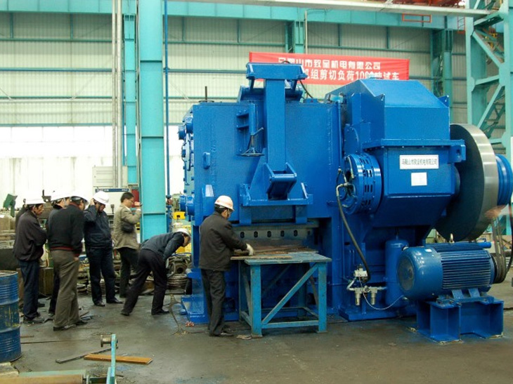 12000KN Cold Shearing Machine
12000KN Cold Shearing Machine
1. Introduction of Equipment
12000KN cold shearing machine is a complete set of mechanical, electrical and hydraulic integrated equipment designed and manufactured jointly with foreign parties on the basis of absorbing the technical characteristics of international advanced shearing machine. The shearing machine is suitable for shearing small bar, flat steel and other rolling materials. It runs smoothly, reliably, and has flat cross section. Its technical specifications and performance are not lower than those of imported similar products. It has a very high cost performance ratio. At the same time, Party B can provide high quality spare parts in time to ensure stable and reliable operation of Party A's equipment.
2. Main technical parameters of 12000KN cold shear
2.1. Bar specifications and steel grades
Shear steel grades: 60Si2CrVAT, GCr15, 42CrMo, 60CrMoBA, 51CrV4.
Maximum shear specifications: round steel_60, flat steel 53x100 (50CrV4); 40x130 (40Cr).
2.2. Main Technical Parameters
Shear force: 15000KN
Shear material: _bmax = 1865 MPa
Maximum Specification of Shear Material: _60
Maximum number of shear roots (_60): nmax = 4 (_b = 1865 MPa)
Maximum Flat Steel Specification: 53x100
Maximum number of sheared flat steel: 2
Shear frequency: 20 times per minute
Shear opening: 210 mm
Blade length: 1400 mm
Edge inclination: 2O
Tool Installation: Flat and Forming Tools
Shear temperature: room temperature (short term 500 oC)
Roller width: 1300mm
Drive motor: 160KW; 1500r/min. AC
Hydraulic Clutch Brake (including Hydraulic Station) (Imported from Germany)
Grease lubrication station, about 23 lubrication points
Cutting machine shape size, length x width x height (mm) 2800 x 6000 x 4500 (mm)
3. 12000KN Cold Shear Structure
The 12000KN cold shearing machine is mainly composed of main motor, belt pulley, flywheel, hydraulic clutch brake, reducer, crankshaft, cutter frame shearing device, frame body, pressing device, tool changer device, hydraulic control system, lubrication system and electronic control system.
3.1. Belt drive device: The main motor transfers motion to the flywheel through a triangular belt (the flywheel is connected with the passive pulley), and its transmission ratio is I1 = 2.3. At this point, the flywheel will save energy.
3.2. Hydraulic clutch, brake and reducer. When the clutch closes, the flywheel transfers motion to the reducer; when the clutch opens, the braking function will be realized, the reducer will stop working and the flywheel will idle. The speed ratio of the reducer is I1 = 30. Hydraulic clutch brake is an imported component. Hydraulic control system is manufactured in China.
3.3. Crankshaft and shearing device. The crankshaft is mounted on the frame with an eccentricity of 105mm. The crank cutter holder is mounted on the crankshaft, and the cutter holder moves up and down in the slideway of the frame. When the clutch closes, the reducer works and drives the crankshaft to rotate. The crank tool holder moves down rapidly from the high position to realize cutting (the blade is installed on the tool holder through the tool holder). After shearing, the crankshaft tool holder moves up with the crankshaft rotation. When moved to high position, the clutch opens and brakes immediately. At this point, the crankshaft stops running. Wait for the next cycle. The opening, closing and braking of clutch are realized by hydraulic system controlled by proximity switch.
3.4. The frame and frame are portal frame structures of cast-welded structures. The crankshaft is mounted in a copper alloy bush on the frame body. The tool holder is mounted in the slideway of the frame body. The slideway is made of copper alloy liner and fitted on the slideway. The skateboard has the function of adjusting the clearance between tool holder and slideway. The normal clearance is 0.1 mm to 0.25 mm. Excessive small or large clearance will affect the quality of section.
3.5. Blade clamping and replacement device. The blade is mounted on the upper and lower tool holders, the upper tool holder is mounted on the tool holder, the lower tool holder is mounted on the frame body, and the tool holder is mounted on the tool holder body, which is pressed by several groups of butterfly springs. Hydraulic cylinders are installed at the rear of each group of butterfly springs. When the blade is replaced, it is controlled by hydraulic force. The piston of the hydraulic cylinder pushes the butterfly spring and loosens the tool seat so that the tool seat can be detached from the tool holder. At this time, the hydraulic cylinder piston in the frame pushes the cutter base more than half. The knife base can be lifted out by the crane. After the new cutter base is hoisted and put in place, the piston of the hydraulic cylinder can pull it into the cutter base and put it in place. At this time, the hydraulic cylinder piston on the butterfly spring rear seat withdraws. The butterfly spring tightens the knife base, thus realizing the replacement of old and new blades.
3.6. Material pressing device. Material pressing device is composed of material pressing head, lever and cylinder. Its function is to fix the shear firmly, so as to achieve stable shear. Its compaction is realized by hydraulic system controlled by electrical apparatus. The position of pressing material can be adjusted according to the size of shearing specification, which is completed by hydraulic cylinder.
3.7. Hydraulic system
3.7.1. The imported hydraulic clutch brake adopts the most advanced hydraulic control system in Germany. The system controls the opening, closing and braking of hydraulic clutch.
3.7.2. The hydraulic system for blade replacement, push-out and pull-in, which utilizes the existing equipment of Party A. The system pressure is 12 MPa.
The hydraulic control of the pressing device and the hydraulic control of the clutch use the same system.
3.8. Lubrication System
Lubrication system (including dry oil pumping station) is grease centralized lubrication. It mainly lubricates sliding bearings and friction pairs, about 23 points. Through the grease lubrication station, grease is fed into each lubrication point through the pipeline through the distributor.
3.9. Electrical control system
The electronic control system is composed of a control cabinet and an operating table. The main motor is in the form of frequency sensitive rheostat. The control points and process control are completed by a Siemens S7-200 programmable controller. Low voltage components are Schneider products.
3.10. Hydraulic cylinder.
Copyright ©Maanshan Zhicheng Electromechanical Co., Ltd Address :Horry town huang village in Anhui province Maanshan huashan area
TEL:0555-3151761 Phone :13705554456 The url :www.ahzcjd.com/
Email
:zcjdgs@163.com For the record,
:皖ICP备19005449号-1 Technical support
:Operation network 
 Mobile
 Applet